|
|
||||
| Bias-T for Cellular & PCS Networks | BT-0819-xxxx | |||
 |
|
Overview
|
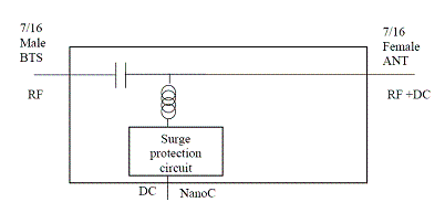
Communication Components, Inc. (CCI) Bias-T’s are designed to combine the DC Bias provided by a Power Distribution Unit for TMA’s (PDU) or other DC Voltage source and the RF signal from other equipment onto the center conductor of a feeder line. This combination of RF and DC provides power to TMA’s (in this case either in the Cellular, or PCS bands), which can then amplify the uplink signal from mobile users. The Bias-T also provides surge protection in case of lightning strikes or other sources or surges. All of the Bias-T’s listed herein utilize 7/16 DIN connectors for the RF Input to the Bias-T and the combined RF + DC Output from the Bias-T. See the mechanical specifications listed on page 2 for details of Model Number versus Input and Output connector type. Technical Description: The Bias-T’s consist of 7/16 DIN Male and/or Female Input (RF) & Output (RF + DC) connectors, and a “NanoC” connector as the DC Bias Input point. The unit also provides protection against lightning strikes via a surge protection circuit. They are all housed in an IP60 rated enclosure with IP68 rated connectors suited to long-life indoor & outdoor (covered) mounting. An optional Power Distribution Unit (PDU) Model # PDU-1819-3DT is available to power up to six TMA’s, and provides monitoring and alarm functions. The PDU is a single (1U) 1.75” x 19” rack mount unit and contains dual redundant power supplies that provide a regulated DC supply voltage for the TMA’s. The Power Distribution Unit monitors the health of the TMA’s and is preprogrammed with the window of acceptable operating currents of all CCI TMA’s. LED’s and dry relay contacts indicate the operational status of each active channel. Output channels are powered if a compatible TMA is connected at the time the front panel reset button is pressed or when the unit is turned on. |
Electrical Specification
| Outdoor AISG Compliant Bias-T(BT-0819-xxxx) Typical Specifications | ||||
| Model | BT-1819-NT | BT-0819-DMDF | BT-0819-DFDF | BT-0819-DFDM |
| Frequency | 1000 - 2000 MHZ | 800 - 2000 MHZ | 800 - 2000 MHZ | 800 - 2000 MHZ |
| RF Impedance | 50 ohms | |||
| Insertion Loss | 0.2 dB | |||
| Return Loss | 20 dB min. Input and Output | |||
| RF Power Handling | 300 W | |||
| IMD | <-120 dBm typical (2 × +43 dBm tones) | |||
| Surge Protection | 8/20us, ±2KA max., 10 strikes each(per IEC-801-5) | |||
| Voltage Rating | + 40 VDC | |||
| Current Rating | 3A max. | |||
Mechanical Specification
| Model | BT-1819-NT | BT-0819-DMDF | BT-0819-DFDF | BT-0819-DFDM |
| Connectors | RF: 7/16 DIN-Male | RF: 7/16 DIN-Male | RF: 7/16 DIN-Female | RF: 7/16 DIN-Female |
| RF+DC 7/16 DIN-Female | RF+DC 7/16 DIN-Female | RF+DC 7/16 DIN-Female | RF+DC 7/16 DIN-Male | |
| DC: "NanoC" external thread male | ||||
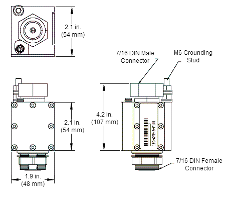
| Dimensions (body only)(W×H×L) | 1.9 × 2.2 × 2.1 in. (48.3 × 55.9 × 53.3 mm) | |||
| Dimensions (inc. connectors)(W×H×L) | 1.9 × 2.2 × 4.2 in. (48.3 × 55.9 × 106.7 mm) | |||
 |
|
| Bias-T Outline Drawing (BT-1819-NT) |
|
|


 Pattern Viewer


