|
|
||||
| TriBand Antenna | HPA65F-KE2A | |||
 |
 |
|
Overview
|
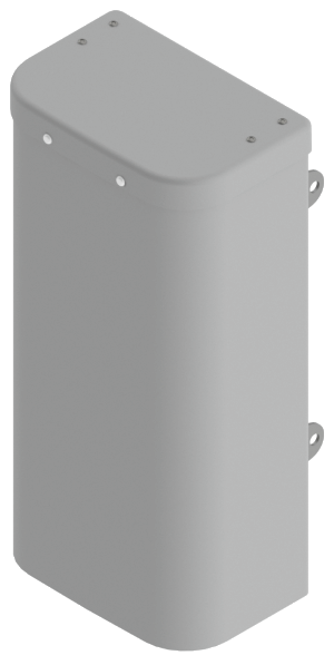
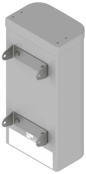
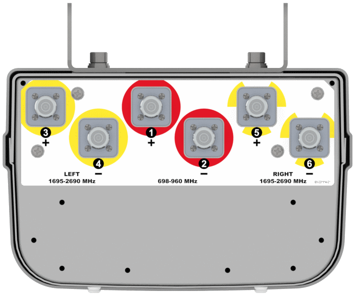
The CCI TriBand is a six port antenna, with four wide high band ports covering 1695-2690 MHz and two wide low band ports covering 698-960 MHz. The CCI TriBand antenna provides the capability to deploy 4×4 Multiple-input Multiple-output (MIMO) in the high band and 2x2 Multiple-input Multiple-output in the low band. CCI antennas are designed and produced to ISO 9001 certification standards for reliability and quality in our state-of-the-art manufacturing facilities. |
Electrical
| Ports | 2 × Low Band Ports for 698-960 MHz | |||
| Frequency Range | 698-806 MHz | 790-862 MHz | 824-896 MHz | 880-960 MHz |
| Gain | 10.8 dBi | 10.8 dBi | 10.9 dBi | 10.9 dBi |
| Azimuth Beamwidth (-3dB) | 65° | 70° | 67° | 61° |
| Elevation Beamwidth (-3dB) | 31.7° | 29.5° | 28.8° | 27.9° |
| Electrical Downtilt | 6° | 6° | 6° | 6° |
| Elevation Sidelobes (1st Upper) | < -20 dB | < -20 dB | < -18 dB | < -17 dB |
| Front-to-Back Ratio @180° | > 35 dB | > 35 dB | > 35 dB | > 35 dB |
| Cross-Polar Discrimination at Peak | > 25 dB | > 25 dB | > 25 dB | > 24 dB |
| Cross-Polar Port-to-Port Isolation | > 25 dB | > 25 dB | > 25 dB | > 25 dB |
| Voltage Standing Wave Ratio (VSWR) | < 1.5:1 | < 1.5:1 | < 1.5:1 | < 1.5:1 |
| Passive Intermodulation (2×20W) | ≤ -153 dBc | ≤ -153 dBc | ≤ -153 dBc | ≤ -153 dBc |
| Input Power Continuous Wave (CW) | 500 watts | 500 watts | 500 watts | 500 watts |
| Polarization | Dual Linear 45° | Dual Linear 45° | Dual Linear 45° | Dual Linear 45° |
| Input Impedance | 50 ohms | 50 ohms | 50 ohms | 50 ohms |
| Lightning Protection | DC Ground | DC Ground | DC Ground | DC Ground |
| BASTA Electrical Specifications* | ||||
| Frequency Range | 698-806 MHz | 790-862 MHz | 824-896 MHz | 880-960 MHz |
| Gain over sub band (dBi) | 10.7 | 10.6 | 10.6 | 10.5 |
| Gain over sub band Tolerance (dB) | 0.2 | 0.2 | 0.2 | 0.3 |
| Azimuth Beamwidth Tolerance (°) | 2.8 | 3.0 | 5.4 | 3.3 |
| Elevation Beamwidth Tolerance (°) | 1.8 | 0.9 | 1.4 | 1.0 |
| Electrical Downtilt Deviation (°) | 2.1 | 1.9 | 1.5 | 1.2 |
| First Upper Sidelobe Suppression (dB) | 17.1 | 17.3 | 19.8 | 13.8 |
| Front-to-Back Ratio over ±20° (dB) | 23.7 | 26.1 | 26.2 | 27.0 |
| Cross-polar Discrimination ±60° (dB) | 10.2 | 11.0 | 10.0 | 10.2 |
| * Electrical specifications follow document "Recommendation on Base Station Antenna Standards" (BASTA) V9.6. All specifications are subject to change without notice. |
||||
| Ports | 4 × High Band Ports for 1695-2690 MHz | ||||
| Frequency Range | 1695-1880 MHz | 1850-1990 MHz | 1920-2180 MHz | 2300-2400 MHz | 2496-2690 MHz |
| Gain | 13.4 dBi | 13.6 dBi | 14.0 dBi | 13.9 dBi | 13.9 dBi |
| Azimuth Beamwidth (-3dB) | 61° | 59° | 59° | 62° | 63° |
| Elevation Beamwidth (-3dB) | 20.7° | 19.3° | 18.5° | 16.5° | 14.5° |
| Electrical Downtilt | 4° | 4° | 4° | 4° | 4° |
| Elevation Sidelobes (1st Upper) | < -15 dB | < -18 dB | < -20 dB | < -19 dB | < -12 dB |
| Front-to-Back Ratio @180° | > 35 dB | > 35 dB | > 35 dB | > 35 dB | > 35 dB |
| Cross-Polar Discrimination at Peak | > 18 dB | > 18 dB | > 19 dB | > 25 dB | > 24 dB |
| Cross-Polar Port-to-Port Isolation | > 25 dB | > 25 dB | > 25 dB | > 25 dB | > 25 dB |
| Voltage Standing Wave Ratio (VSWR) | < 1.5:1 | < 1.5:1 | < 1.5:1 | < 1.5:1 | < 1.5:1 |
| Passive Intermodulation (2×20W) | ≤ -153 dBc | ≤ -153 dBc | ≤ -153 dBc | ≤ -153 dBc | ≤ -153 dBc |
| Input Power Continuous Wave (CW) | 300 watts | 300 watts | 300 watts | 300 watts | 300 watts |
| Polarization | Dual Linear 45° | Dual Linear 45° | Dual Linear 45° | Dual Linear 45° | Dual Linear 45° |
| Input Impedance | 50 ohms | 50 ohms | 50 ohms | 50 ohms | 50 ohms |
| Lightning Protection | DC Ground | DC Ground | DC Ground | DC Ground | DC Ground |
| BASTA Electrical Specifications* | |||||||
| Frequency Range | 1695-1880 MHz | 1850-1990 MHz | 1920-2180 MHz | 2300-2400 MHz | 2496-2690 MHz | ||
| Gain over sub band (dBi) | 12.4 | 12.9 | 13.2 | 13.4 | 13.4 | ||
| Gain Tolerance over sub band (dB) | 0.8 | 0.7 | 0.7 | 0.6 | 0.6 | ||
| Azimuth Beamwidth Tolerance (°) | 5.1 | 4.2 | 4.5 | 8.3 | 10.1 | ||
| Elevation Beamwidth Tolerance (°) | 3.8 | 2.8 | 2.8 | 2.4 | 2.9 | ||
| Electrical Downtilt Deviation (°) | 1.1 | 1.0 | 1.1 | 0.9 | 1.1 | ||
| First Upper Sidelobes Suppression (dB) | 9.5 | 11.8 | 12.8 | 11.6 | 8.6 | ||
| Upper Sidelobe Suppression Peak to 20° (dB) | 16.6 | 17.4 | 16.5 | 15.6 | 9.0 | ||
| Front-to-Back Ratio over ±20° (dB) | 27.1 | 26.1 | 27.0 | 27.1 | 30.1 | ||
| Cross-polar Discrimination at ±60° (dB) | 8.7 | 9.0 | 8.2 | 7.1 | 8.2 | ||
| * Electrical specifications follow document "Recommendation on Base Station Antenna Standards" (BASTA) V9.6. All specifications are subject to change without notice. |
|||||||
Mechanical
| Dimensions (L×W×D) | 24.3×11.9×7.6 in (618×303×193 mm) |
| Survival Wind Speed | > 150 mph (> 241 kph) |
| Front Wind Load | 62 lbs (276 N) @ 100 mph (161 kph) |
| Side Wind Load | 40 lbs (180 N) @ 100 mph (161 kph) |
| Equivalent Flat Plate Area | 2.4 ft2 (0.2 m2) |
| Weight* | 14.3 lbs (6.5 kg) |
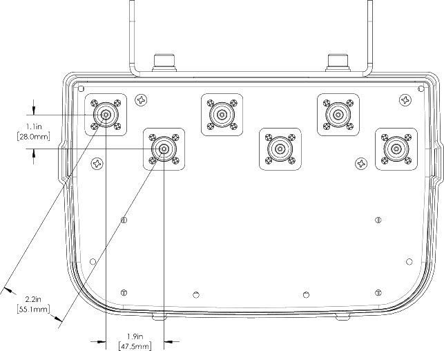
| Connector | 6× 4.3-10 female |
| Mounting Pole | 2 to 5 in (5 to 12 cm) |
| * Weight excludes mounting |
| Bottom View | HPA65F-KE2AA |
 |
| Connection Spacing Diagram | HPA65F-KE2AA |
 |
Typical Antenna Patterns
| For detailed information on additional antenna patterns, contact customer support at | ||
 |
 |
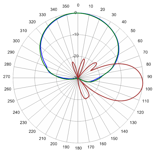 |
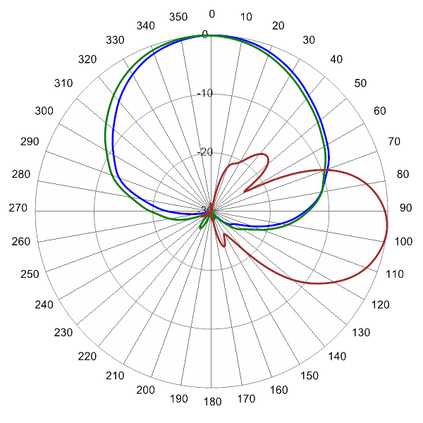
| 704 MHz Azimuth with Elevation 6° | 850 MHz Azimuth with Elevation 6° | |
 |
 |
|
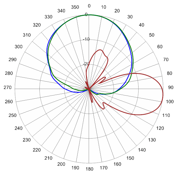
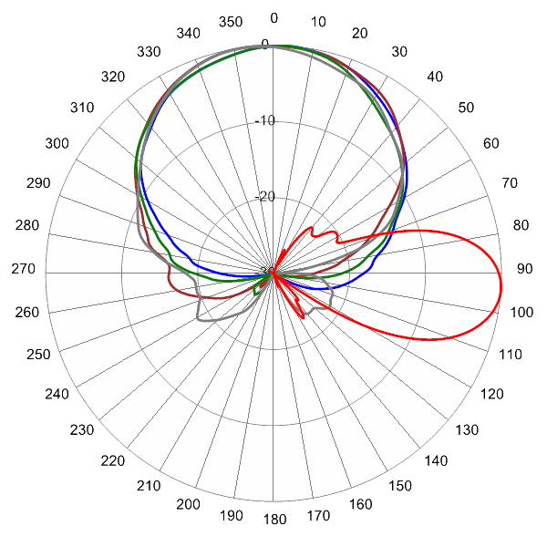
| 945 MHz Azimuth with Elevation 6° |
 |
 |
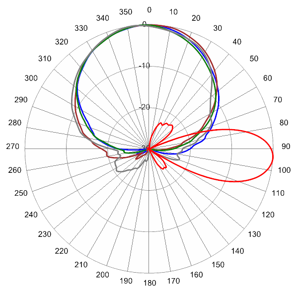 |
| 1710 MHz Azimuth with Elevation 4° | 1970 MHz Azimuth with Elevation 4° | |
 |
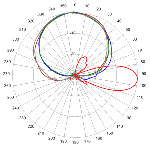 |
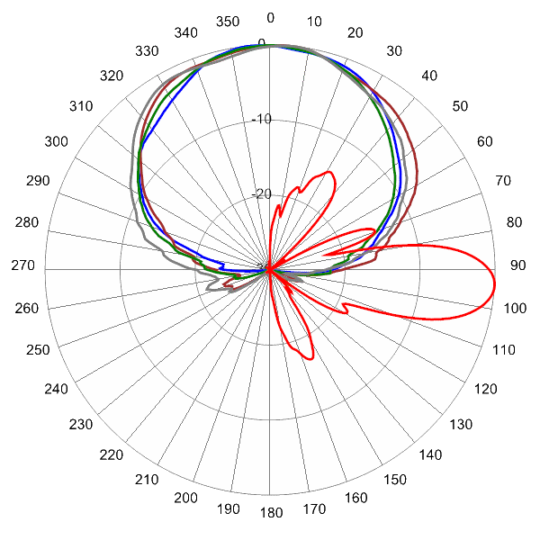 |
| 2155 MHz Azimuth with Elevation 4° | 2500 MHz Azimuth with Elevation 4° |
| MBK-03 | MBK-03 Mounting Kit |
Parts & Accessories
| HPA65F-KE2AA-K | Two foot (0.6 m) TriBand antenna with 65° azimuth beamwidth, 4.3-10 female connectors and MBK-03 mounting bracket |
| MBK-03 | Mounting bracket kit (top and bottom) with 0° to 10° mechanical tilt adjustment |


 Pattern Viewer
