|
|
||||
| GPS Over Fiber System | GPS-FOS-T1R8-SA3 | |||
 |
|
Overview
|
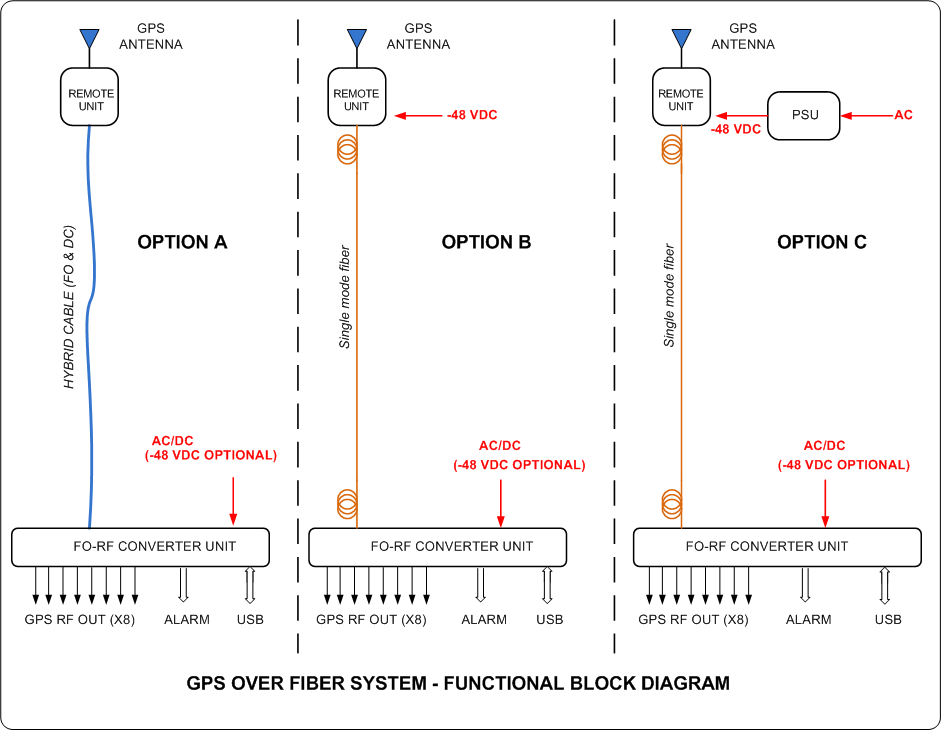
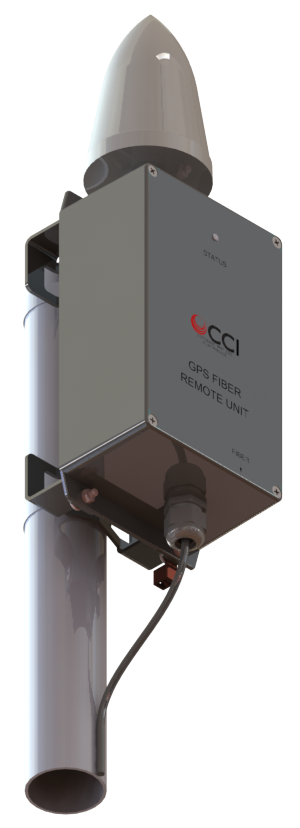
Communication Components, Inc. GPS Over Fiber Systems provides an innovative and cost effective means of routing the GPS signal over a fiberoptic network to a remote Base Station location. This system is ideal for CRAN (Centralized Radio Access Network) deployments and In-building DAS installations where the Base Station is located in a remote location with no direct availability of GPS signal. Technical Description: The GPS-FO-Tx-1 GPS to Fiberoptic Transmitter upconverts the GPS RF signal from any active GPS antenna to the optical band to enable transmission of the signal up to 4 kilometers over a single fiberoptic line. GPS Antenna bias current is provided and comprehensive alarm detection and reporting of the GPS antenna and the fiberoptic transmitter are delivered over the single fiber to the companion Fiberoptic to GPS Receiver for local display and monitoring. |
Electrical
| Description | Fiber Converter Unit | Outdoor Remote Unit |
| # of RF Channels | 8 RX (GPS-FO-Rx-8P) | 1 TX (2 TX W/Redundancy) |
| Band Supported | GPS/GLONASS | |
| RX Noise Figure | N/A | 5 dB max. |
| RX Input IP3 (IIP3) | N/A | 30 dBm max. |
| RX RF Return Loss | N/A | 14 dB min. |
| Antenna Power Supply | N/A | +5VDC, 70 mA max. |
| TX RF Output Power | -70 dBm max. | N/A |
| TX Output IP3 (OIP3) | +10 dBm max. | N/A |
| TX Other Spurious Outputs | -75 dBm max. | N/A |
| RF Link Budget to Antenna | N/A | +13 dB |
| Optical Ports | SMF, SC/APC | SMF, SC/APC |
| Fiber Category | Single Mode (OS2) | |
| Fiber Data Rate | 100 GB max. | |
| Fiber Core/Cladding Dimension | 9/125 um | |
| Delay Efficiency | 100 nS max. | |
| Optical Budget | Up to 4 Km @ 1310 nm | |
| Alarms | LEDs, Dry Contact Closures, USB readout | LED |
| Laser warning:Invisible Laser Radiation emitting from Optical connector. Avoid direct exposure to beam. 20 mW max. A 1310 and 1550 nm CDRH Class IIIB. | ||
| General Characteristics | Fiber Converter Unit | Outdoor Remote Unit |
| Power Consumption (@ 48 VDC) | 350 mA Max. (Standalone) | 250 mA Max., 200 mA Typ. (includes 70 mA @ 5 VDC provided to the GPS Antenna LNA) |
| Power Consumption | 600 mA Max. (includes power supplied to outdoor unit) | |
| Input Fuse | 2A Resettable | N/A |
| Output Fuse | 1A Resettable (on 48 VDC Output Line) | N/A |
| Description | GPS-ANT-28-3 (GPS Antenna) |
| Frequency Range | 1575.42 ± 10 MHz |
| LNA Gain | 26.5 dB ± 3 dB |
| Element Gain | 3.5 dBic |
| Out of Band Rejection | ≥ 65 dB @ 1559 MHz, ≥ 65 dB @ 1625 MHz |
| VSWR (Return Loss) | ≤ 1.5:1 (≥ 14.0 dB) |
| Noise Figure | ≤ 4.0 dB @ 25°C (typ.), ≤ 4.5 dB @ 25°C (max.) |
| Current Draw | ≤ 40 mA @ 5V |
| ESD Proterction | 15 kV |
| DC Voltage | Operating: 3.3-12.0 VDC (regulated), Survival: 24 VDC |
| Nominal Impedance | 50 ohms |
| Polarization | Right hand circular |
| Dimensions | 5.0" (H) x 3.2" (D) (126 mm (H) x 81 mm (D)) |
| Weight | 0.6 lbs. (0.3 kg) |
| Temperature Range | -40°C to +85°C |
| Humidity | 95% |
| Description | GPS-AC-48V (Optional AC to DC Power Supply Specifications) | GPS-ACC-48V (Optional Outdoor AC to DC Power Supply Specifications) |
| DC Output Voltage (Nominal) | 48 VDC | |
| Rated Current | 1.9 A | 1.3 A |
| Rated Power | 90.24W | 62.4W |
| Output Voltage Stability | ±1.0% | |
| Input Voltage Range | 90 - 264 VAC | |
| Input Frequency Range | 47 - 63 Hz | |
| Power Factor (at full load) | 90% typical | 98% (115 VAC), 95% (230 VAC) |
| Efficiency | 89.5% typ. (115 VAC), 91% (230 VAC) | 90.5% typ. (115 VAC), 92% (230 VAC) |
| AC Current | 0.95A typ.(115 VAC), 0.5A (230 VAC) | 0.64A typ.(115 VAC), 0.32A (230 VAC) |
| Inrush Current | Cold Start 30A typ. (twidth = 550uS measured at 50% Ipeak) at 115 VAC, Cold Start 60A typ. (twidth = 550uS measured at 50% Ipeak) at 230 VAC | Cold Start 55A typ. (twidth = 265uS measured at 50% Ipeak) at 230 VAC |
| Overcurrent Protection | 95-108% (Constant current limiting), recovers automatically after fault condition is removed) | |
| Short Circuit Protection | Hiccup mode (recovers automatically after fault condition is removed) | |
| Over Voltage Protection | 54-60 V (Shut down output voltage, re-power on to recover) | 54-65 V (Shut down output voltage, re-power on to recover) |
| Over Temperature | Shut down output voltage, re-power on to recover | |
| IEC Standard 60529 (Ingress Protection) | IP67 (Main Body only) | IP67 |
| UL Certification | UL | UL, ULC |
| Working Temperature | -40°C - +70°C | Tcase = -40°C - +80°C |
| Working Humidity | 20 - 95 % RH (non-condensing) | |
| Storage Temperature, Humidity | -40°C - +80°C, 10 - 95 % RH | |
| Temp. Coefficient | ±0.03%/°C (0°C - 50°C) | ±0.03%/°C (0°C - 60°C) |
| Withstanding Voltage | I/P-O/P:3.75 KVAC | I/P-O/P:3.75KVAC I/P-FG:2KVAC O/P-FG:1.5KVAC |
| Isolation Resistance | I/P-O/P:100M Ohms (@500 VDC, 25°C, 70% RH) | I/P-O/P, I/P-FG, O/P-FG:100M Ohms (@500 VDC, 25°C, 70% RH) |
| EMC Emission | Compliance to FCC Part 15 | Compliance to BS EN/EN61000-4-2,3,4,5,6,8,11; BS EN/EN61547, light industry level (surge immunity Line-Earth 4KV, Line-Line 2KV),EAC TP TC 020 |
| MTBF | 292.8K hrs. minimum | 338K hrs. minimum |
| Dimensions | 171 x 63 x 37.5 mm (6.73 x 2.48 x 1.48") |
171 x 61.5 x 36.8 mm (6.73 x 2.42 x 1.45") |
| Weight | 0.83 kg (1.82 Lbs.) | 0.73 kg (1.6 Lbs.) |
Environmental
| Operating Temperature | 0˚C to +50˚C (Indoor FO/GPS Receiver) / -20˚C to +50˚C (Outdoor GPS/FO Transmitter) |
| Enclosure | Indoor FO/GPS Receiver (IP11) / Outdoor GPS/FO Transmitter (IP67) |
| Relative Humidity | 0 - 45 % (Indoor) / 0 - 99% (Outdoor) |
| MTBF | >500,000 hours |
| Lightning Protection | 8/20uS, ±20KA max., 10 strikes each, IEC61000-4-5 |
Mechanical
| Outdoor GPS to Fiberoptic Transmitter | |
| GPS Antenna Input Connector | 1 x N-Type male |
| Fiberoptic Connector | SC/APC |
| DC Input Connector | 2 Position Terminal Block |
| Dimensions (with connectors & panel) - (HxWxD) | 9.13 x 4.80 x 2.95 in (232 x 122 x 75 mm) |
| Weight (w/o Bracket) | < 2.75 lb |
| Mounting | Pole/Wall Mount |
| Outdoor Fiberoptic to GPS Receiver | |
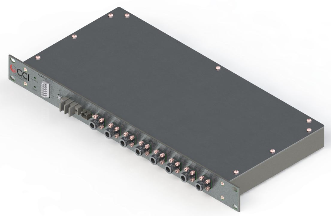
| GPS RF Output RF Connectors | 8 x N-Type female (GPS-FO-Rx-8) |
| Fiberoptic Input Connector | SC/APC |
| DC Input Connector | 2 Position Terminal Block |
| DC Output Connector | 2 Position Terminal Block |
| Communications & Control Connector | USB |
| Alarm Connector | 6 Position Terminal Block |
| Dimensions - (H x W x D) - with Faceplate | 1.72 x 19 x 8 in (43.69 x 482.6 x 203.2 mm) |
| Dimensions - (H x W x D) - Body Only | 1.72 x 17 x 8 in (43.69 x 431.8 x 203.2 mm) |
| Weight | 6 lbs |
| Mounting | 19 in. rack mountable 1U |
 |
|
| GPS-FO-Tx-1A (GPS to Fiberoptic Transmitter) Drawing |
Parts & Accessories
| GPS-FOS-T1R8-SA3 | The GPS Over Fiber System includes one outdoor GPS to Fiberoptic Transmitter and one 8 Channel Indoor Fiberoptic to GPS Receiver |
| GPS-FOS-T1R8-SA3-K | The GPS Over Fiber System includes one outdoor GPS to Fiberoptic Transmitter and one 8 Channel Indoor Fiberoptic to GPS Receiver and one outdoor 48 VDC AC to DC Power Supply |
| GPS-FOS-T1R8-SA3P | The GPS Over Fiber System includes one outdoor GPS to Fiberoptic Transmitter and one 8 Channel Indoor Fiberoptic to GPS Receiver with -48V positive ground option |
| GPS-FOS-T1R8-SA3P-K | The GPS Over Fiber System includes one outdoor GPS to Fiberoptic Transmitter and one 8 Channel Indoor Fiberoptic to GPS Receiver with -48V positive ground option and one outdoor 48 VDC AC to DC Power Supply |
| GPS-FO-Tx-1A | Outdoor GPS to Fiberoptic Transmitter |
| GPS-ANT-28-3 | GPS Antenna |
| GPS-FO-Rx-8 | 8 Channel Indoor Fiberoptic to GPS Receiver |
| GPS-FO-Rx-8P | 8 Channel Indoor Fiberoptic to GPS Receiver with -48V positive ground option |
| GPS-AC-48 | Optional 48V AC to DCPower Supply |
| GPS-ACC-48 | Optional Outdoor 48V AC to DCPower Supply with Canadian UL Certification |
|
|


 Pattern Viewer


