|
|
||||
| PiMPro Tower Series | PiMPro Tower 900 | |||
 |
|
Overview
|
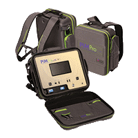
CCI's PiMPro Tower Series is the first truly portable family of Passive Intermod (PIM) analyzers. All PiMPro Tower analyzers have real world 40W × 2 output power capability, with a sensitivity of -135 dBm, and can run on battery power for over three hours. The PiMPro Tower 900 has the ability to cover the 900 MHz band, 880-980 MHz. The analyzer's excellent measurement sensitivity (-135 dBm) as well as its ability to set transmit tone levels down to 20 dBm (100 mW) × 2 makes it the perfect resource for conventional cell sites as well as in-building Distributed Antenna System (DAS) requirements. The Tower Series demonstrates the perfect synergy of CCI’s world class in-house engineering design expertise for both filters and amplifiers. Each light weight and compact unit is protected by a reinforced backpack case which can easily strap to a climber’s back for top-of-the-tower performance testing. The unit can be safely secured to most any tower structure with its integrated industrial grade clips. Each unit features a superior quality bright TFT capacitive large 8.0 inch (203 mm) screen that provides a very friendly user interface. CCI’s simple GUI combined with a powerful CPU make for fast measurement acquisition and site data storage. The portable construction, designed with durable ruggedness and reliability first and foremost, PiMPro Tower Series will prove to be a valuable investment for years to come. |
|
Most LTE sites are configured with radios set at 40 watts or more per carrier and each site can have as many as four carriers per sector. This means that PIM testing at anything less than 40W × 2 will not accurately simulate live network traffic and is likely to understate actual site PIM levels. The PiMPro Tower Series' 40 watt × 2 power level allows for realistic PIM level testing in the field and at the tower top. The analyzer provides precise measurement of the 3rd and 5th order intermods of any system or component under high-power conditions. In addition to passive intermodulation measurements, the unit will provide VSWR and Return Loss values. PiMPro can be used to verify the integrity of individual passive components including connectors, cable assemblies, antennas, filters, making it an integral performance tool for site and tower technicians. |
Electrical Specifications
| PiMPro Tower 900 | ||
| Receive Frequency | RX1: 880 - 915 MHz | |
| Transmit Frequency | TX1: 925 - 937.5 MHz; TX2: 951.5 - 980 MHz | |
| Transmitter | Frequency Accuracy | ±1 ppm @ +23°C; Stability ±1 ppm -10°C to +55°C |
| Frequency Aging | ±1 ppm/yr | |
| Power Accuracy | 0.3 dB | |
| Frequency Step Size | 200 kHz | |
| Power Resolution | 0.1 dB | |
| Adjustable Power Range | 20 to 46 dBm × 2 (100 mW to 40 W × 2) | |
| Receiver | Residual Intermod Level | -120 dBm (-125 dBm Typical) |
| Measurement Range | -60 to -140 dBm | |
| Noise Floor | -136 dBm | |
| Reverse Power Protection | 13 dBm (20 mW) continuous | |
| Measurement Mode | Measurement Method | One Port, Reverse PIM |
| Real Time PIM | 3rd & 5th PIM | |
| Return Loss | Measured in dB | |
| PIM vs Time | 3rd & 5th PIM | |
| PIM Location (PIMPoint) | Distance in Feet or Meters with VP Settings | |
| Distance to Fault/Cable Loss | One Port Open-Short Calibration | |
| RX Interference | Receive Only Mode - Noise Floor Measurements | |
| Noise Floor Measurement | Up-Link noise level with TX off | |
| Frequency Sweep | Frequency Response | |
| DAS Feature | Low power single tone transmit to evaluate connectivity and path losses, or external interference | |
| Measurement Range | Return Loss | Directivity >20 dB; Resolution >0.1 dB |
| VSWR | Measurement Range 9:1 to 1.1:1; Resolution >0.1 dB | |
| Cable Loss | Measurement Range 0 to 12 dB; Resolution >0.1 dB | |
| Distance to Fault | VSWR Range 17:1 to 1.02:1; RL Range 0 to 40 dB | |
| System | Battery | >3 hours (Full Charge) |
| Power | AC & DC (AC 90 - 256 V, 50 - 60 Hz) | |
| Alarms | Audio & Visual Display | |
| Display Size & Type | 8.0" (203.2 mm) Capacitive TFT | |
| Data Ports | 3 - USB 2.0, 1 - Ethernet LAN Port | |
| Remote Control | WiFi Enabled (802.11n) | |
| Battery Power | 28 VDC | |
| Battery Capacity | 3.5 AH (99.4 WH) | |
| Battery Type | Li-Polymer Removable Battery Pack | |
| Electrical | Max Power Consumption | <340 W |
Measurement & Configuration
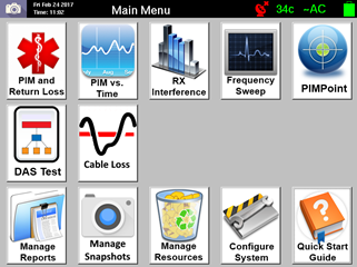 |
Main Screen Main boot-up screen shows all measurement features in graphic icon format. Selecting the appropriate icon opens the associated measurement screen. This screen also provides access to the complete system configuration, report management and access to an abbreviated user manual. |
|
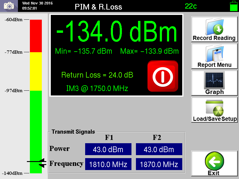 |
PIM & Return Loss PiMPro’s main measurement screen provides instantaneous PIM measurement in both dBc or dBm. The large display flashes to annunciate the presence of RF power at the output connector. Pass/Marginal/Fail Limits, Output Power, Frequency and IM settings originate from this screen. PiMPro’s unique Return Loss diagnostic feature at high transmit (TX) power, quickly points out open cables. |
|
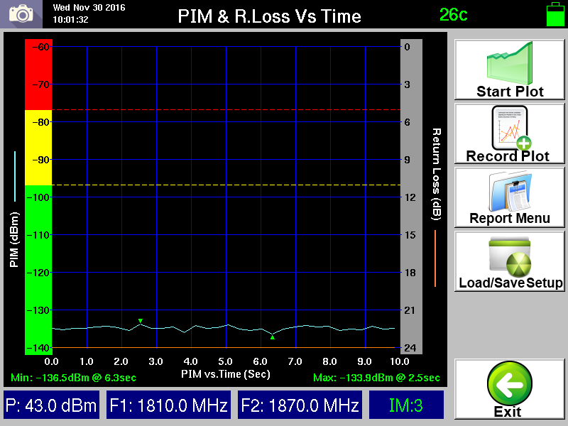 |
PIM vs Time Measurement The PIM vs Time dynamic measurement mode features a graphical representation of PIM as a function of time. Time scale can be set from 10 seconds to 4 minutes. The PiMPro Return Loss feature is also available on this screen. |
|
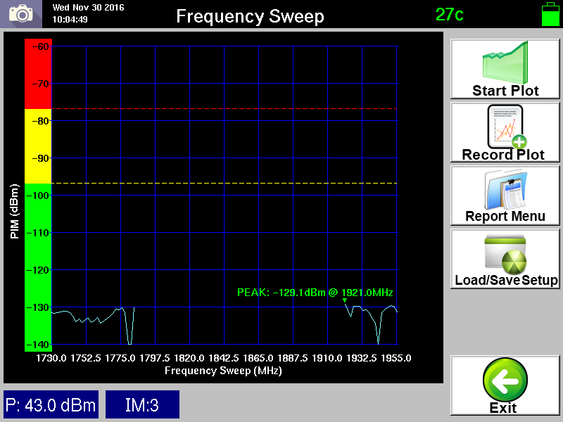 |
Frequency Sweep PiMPro displays a swept receive (RX) PIM range by sweeping the TX carriers from end to end within the set frequency band. PIM frequency response is displayed, exposing the worst case PIM level and the contributing frequencies. Users can immediately transfer the graph to the PIM vs Time feature and run a new test to isolate the causes of the specific PIM. |
|
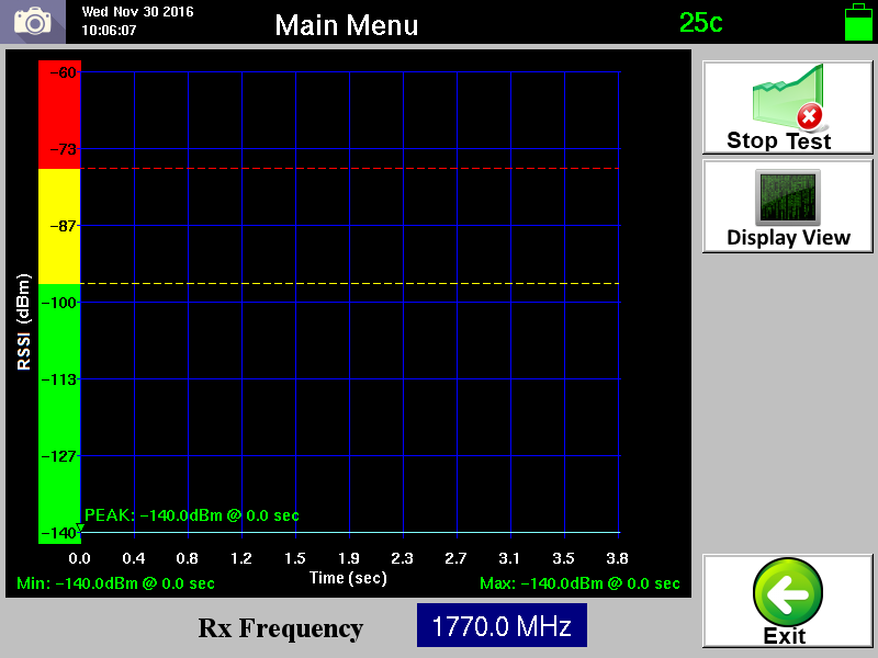 |
DAS Measurement TX Function: Generates in the radio’s DL frequency a low power single tone anywhere within the DAS network (usually from the head-end) to evaluate RF connectivity and path losses. With three hours of TX time a technician can roam a DAS installation with a spectrum analyzer and detect systemic RF anomalies RX Function: Used as a receiver tool to evaluate ideal areas within a given location to position DAS antennas. Using a simple Yagi or planar antenna for external interference evaluation, a DAS antenna can be optimally positioned to locations where external interference is lowest. |
|
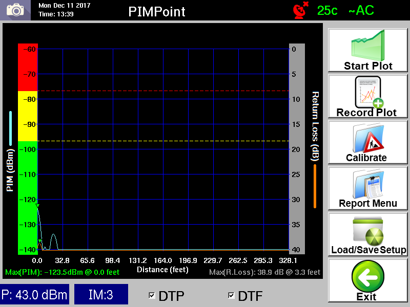 |
Simultaneous DTF and PiMPoint Measurements After a simple calibration procedure, the unit allows simultaneous measurements (superimposed on the same screen) of Distance to Fault and PiMPoint (PIM vs. Distance). All the measurements are done from a single port, no need to disconnect to a separate measurement port. |
|
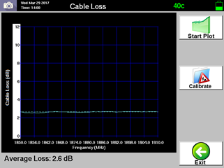 |
Cable Insertion Loss Cable insertion loss measurements are accurately performed in the uplink of the PIM analyzers band. A simple open-short calibration is all that is required for this one port measurement. Much of the measurement error is removed with the displayed average insertion loss value. |
|
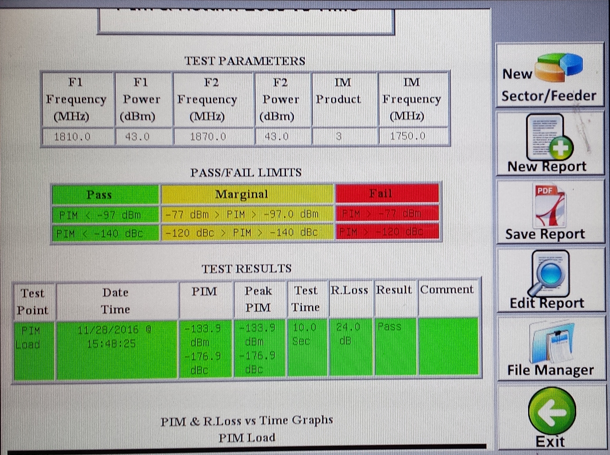 |
Report Generator Report data for all measurement modes can be stored in either, HTML or PDF file format. Users can concatenate a limitless series of measurements with different sector, feeder, color codes, as one single PDF file. Reports can be saved in PiMPro’s internal memory or to external USB memory from the unit’s front panel. |
|
Accessories
| Included In: | |||||||
| Sys Pkg | Econ Pkg | PPT-AK | PPT-EAK | ||||
 |
 |
PP-AK-CBL-DMDM | Low PIM Male DIN to Male DIN jumper cable 3/8“ 3 m (10 ft) length | X | X | X | X |
| PP-AK-CBL-DMDF | Low PIM Male DIN to Female DIN jumper cable 3/8“ 3 m (10 ft) length | X | X | ||||
| PP-AK-PSTAN-80 | PIM Standard - 80 dBm | X | X | X | X | ||
| PP-AK-DMDM | Low PIM 7–16 DIN Male to Male Adapter | X | X | ||||
| PP-AK-DFDF | Low PIM 7–16 DIN Female to Female Adapter | X | X | ||||
| PP-AK-DMMF | Low PIM 7–16 DIN Male to 4.3-10 Female Adapter | X | X | ||||
| PP-AK-DMMM | Low PIM 7–16 DIN Male to 4.3-10 Male Adapter | X | X | ||||
| PPT-OS | Open - Short Standard | ||||||
| PP-AK-LOAD | Low PIM Termination Load < -168 dBc with both Male and Female 7–16 DIN | X | X | X | X | ||
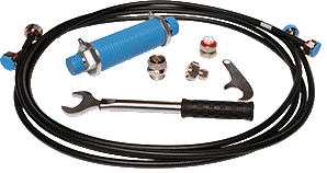
| PP-AK-TORW | Torque Wrench for 7–16 DIN Connector | X | X | X | X | ||
| PP-AK-ADJW | Adjustable Wrench | X | X | X | X | ||
 |
PP-AK-FIXW | Small 32 mm Wrench for 7–16 DIN | X | X | |||
| PPT-AK-BATT1 | Rechargeable Battery (28.8 VDC, 3450 mAh, 99.4 WH) | X | X | ||||
| PPT-AK-BATT | Rechargeable Battery (28.8 VDC, 4500 mAh, 130.0 WH) | ||||||
| PP-AKT-CHRGR | Battery Charger | X | X | ||||
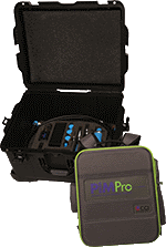
| AKC | PiMPro Tower Accessory Kit Case | X | X | ||||
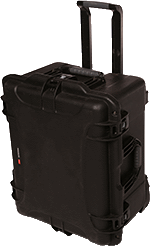
| PPT-TC | Tower Transport Case | X | X | ||||
| PPT-AC-ADPT | AC/DC Power supply | ||||||
| * All accessory kit components and cables have low PIM connectors, with PIM level <-122 dBm | |||||||
Parts & Accessories
| PIMPRO TOWER 900 | PiMPro Tower 900 |
| Accessories Included | Power Cord, Operation Manual |
| Additional operational accessories available individually or in convenient Universal Kit configurations. | |
| Tower 900B SP | PiMPro Tower 900 SP: Includes PiMPro Tower 900, Tower Accessory Kit, Transport Case |
| PPT-11 | Option 11 - GPS Capability |
| PPT-21 | Option 21 - DTF Measurement, includes open/short standard |
| PPT-31 | Option 31 - Wi-Fi Remote Control App |
| PPT-41 | Option 41 - SCPI Programmability |
| PPT-TC | PiMPro Tower Transport Case |
| PPT-AK | PiMPro Tower Accessory Kit in soft carrying case |
| PPT-EAK | PiMPro Tower Economy Accessory Kit in soft carrying case |
| PPT-EAKTC | PiMPro Tower Accessory Kit in Transport Case |
| EW1 | One year extended warranty for PiMPro Tower |
| EW2 | Two year extended warranty for PiMPro Tower |
| EW4 | Four year extended warranty for PiMPro Tower |
|
|


 Pattern Viewer


