|
|
||||
| Small Cell ODA 65°x65° Antenna | ODA65F-KE1A |
|||
 |
 |
|
Antenna Pattern
|
| In the Americas | |
| Sales | |
| +1 (201) 342-3338 phone | |
| +1 (201)-342-3339 fax | |
| 89 Leuning Street | |
| South Hackensack, NJ 07606 | |
| USA | |
| Customer Service | |
| +1 (201) 342-3338 phone | |
| +1 (201)-342-3339 fax | |
| 89 Leuning Street | |
| South Hackensack, NJ 07606 | |
| USA | |
| Technical Support | |
| +1 (201) 342-3338 phone | |
| +1 (201)-342-3339 fax | |
| 89 Leuning Street | |
| South Hackensack, NJ 07606 | |
| USA | |
|
|
||||
| Small Cell ODA 65°x65° Antenna | ODA65F-KE1A |
|||
 |
 |
|
|
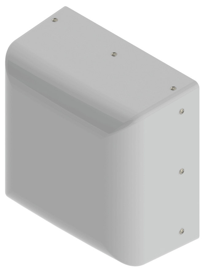
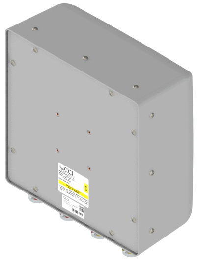
The CCI multiband 65° x 65° array is a four port antenna Small Cell antenna, with two wide high band ports covering 1695-2690 MHz and two wide low band ports covering 694-960 MHz. The CCI 65° x 65° antenna provides 2x2 Multiple-input-Multiple-output (MIMO) across the low band and high band ports. The CCI 65° x 65° Small Cell antenna is an ideal choice for Microcells, Small Cell and oDAS densification deployments in urban and suburban environments where antenna size and count are restricted. The CCI 65° x 65° Small Cell antenna provides a fixed 0° EDT, across all frequencies. |
| Ports | 2 × Low Band Ports for 694-960 MHz | |||||
| Frequency Range | 694-806 MHz | 824-896 MHz | 880-960 MHz | |||
| Gain1 | 8.2 dBi | 8.2 dBi | 8.6 dBi | |||
| Gain (Average)2 | 7.9 dBi | 8.0 dBi | 8.4 dBi | |||
| Azimuth Beamwidth (-3dB) | 70° | 65° | 59° | |||
| Elevation Beamwidth (-3dB) | 79° | 74° | 68° | |||
| Electrical Downtilt | 0° | 0° | 0° | |||
| Front-to-Back Ratio @180° | > 25 dB | > 22 dB | > 22 dB | |||
| Cross-Polar Discrimination (at Peak) | > 24 dB | > 20 dB | > 18 dB | |||
| Cross-Polar Port-to-Port Isolation | > 22 dB | > 22 dB | > 18 dB | |||
| Voltage Standing Wave Ratio(VSWR) | < 1.6:1 | < 1.6:1 | < 1.6:1 | |||
| Passive Intermodulation (2×20W) | ≤ -150 dBc | ≤ -150 dBc | ≤ -150 dBc | |||
| Input Power Continuous Wave (CW) | 80 watts | 80 watts | 80 watts | |||
| Polarization | Dual Pol 45° | Dual Pol 45° | Dual Pol 45° | |||
| Input Impedance | 50 ohms | 50 ohms | 50 ohms | |||
| Lightning Protection | DC Ground | DC Ground | DC Ground | |||
| 1Peak gain across sub-bands. 2Electrical specifications follow document "Recommendation on Base Station Antenna Standards" (BASTA) V9.6. |
||||||
| Ports | 2 × High Band Ports for 1695-2690 MHz | |||||
| Frequency Range | 1695-1880 MHz | 1850-1990 MHz | 1920-2180 MHz | 2300-2400 MHz | 2496-2690 MHz | |
| Gain1 | 8.6 dBi | 8.6 dBi | 8.5 dBi | 8.6 dBi | 9.3 dBi | |
| Gain (Average)2 | 8.5 dBi | 8.4 dBi | 8.4 dBi | 8.4 dBi | 9.0 dBi | |
| Azimuth Beamwidth (-3dB) | 57° | 61° | 64° | 70° | 61° | |
| Elevation Beamwidth (-3dB) | 62° | 64° | 68° | 73° | 60° | |
| Electrical Downtilt | 0° | 0° | 0° | 0° | 0° | |
| Front-to-Back Ratio @180° | > 32 dB | > 32 dB | > 32 dB | > 32 dB | > 35 dB | |
| Cross-Polar Discrimination (at Peak) | > 28 dB | > 28 dB | > 28 dB | > 26 dB | > 26 dB | |
| Cross-Polar Port-to-Port Isolation | > 25 dB | > 25 dB | > 25 dB | > 25 dB | > 25 dB | |
| Voltage Standing Wave Ratio(VSWR) | < 1.75:1 | < 1.75:1 | < 1.75:1 | < 1.75:1 | < 1.75:1 | |
| Passive Intermodulation (2×20W) | ≤ -150 dBc | ≤ -150 dBc | ≤ -150 dBc | ≤ -150 dBc | ≤ -150 dBc | |
| Input Power Continuous Wave (CW) | 80 watts | 80 watts | 80 watts | 80 watts | 80 watts | |
| Polarization | Dual Pol 45° | Dual Pol 45° | Dual Pol 45° | Dual Pol 45° | Dual Pol 45° | |
| Input Impedance | 50 ohms | 50 ohms | 50 ohms | 50 ohms | 50 ohms | |
| Lightning Protection | DC Ground | DC Ground | DC Ground | DC Ground | DC Ground | |
| 1Peak gain across sub-bands. 2Electrical specifications follow document "Recommendation on Base Station Antenna Standards" (BASTA) V9.6. |
||||||
| Dimensions (L×W×D) | 11.8×11.8×6.1 in (300×300×156 mm) |
| Survival Wind Speed | > 125 mph (> 201 kph) |
| Front Wind Load | 30 lbs (132 N) @ 100 mph (161 kph) |
| Side Wind Load | 15 lbs (69 N) @ 100 mph (161 kph) |
| Equivalent Flat Plate Area | 1.2 ft2 (0.1 m2) |
| Weight* | 4.6 lbs (2.1 kg) |
| Connector | 4 × 7-16 DIN female long neck or 4.3-10 Female |
| Wall Mount (fixed) | 0.375 in (10 mm) diameter hardware recommended |
| Wall Mount Tilt | 0.375 in (10 mm) diameter hardware recommended |
| Mounting Pole | 2 to 4.5 in (5 to 11 cm) |
| * Weight excludes mounting |
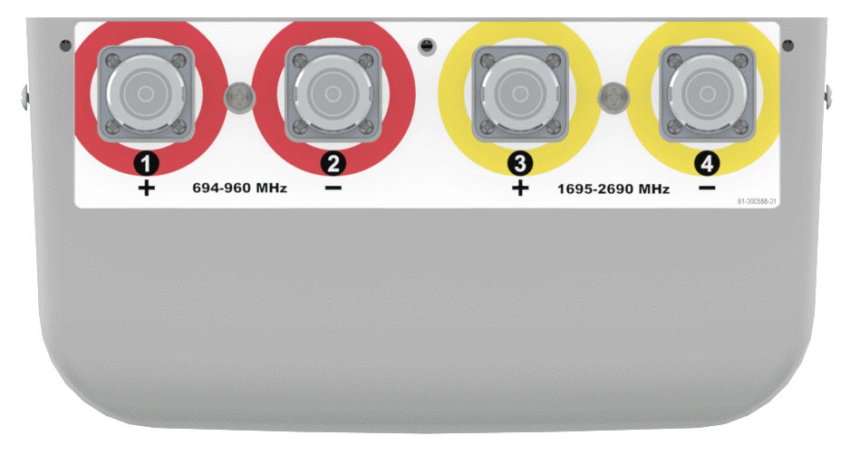
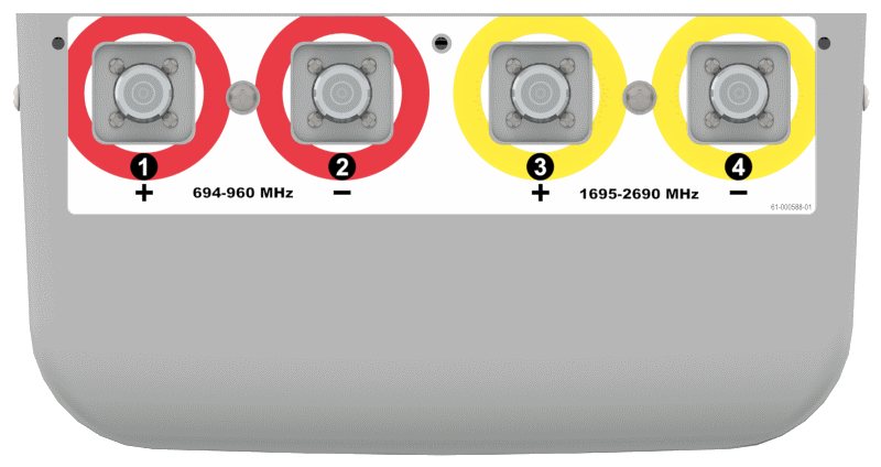
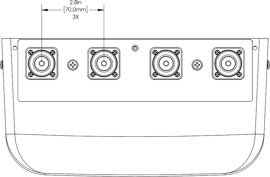
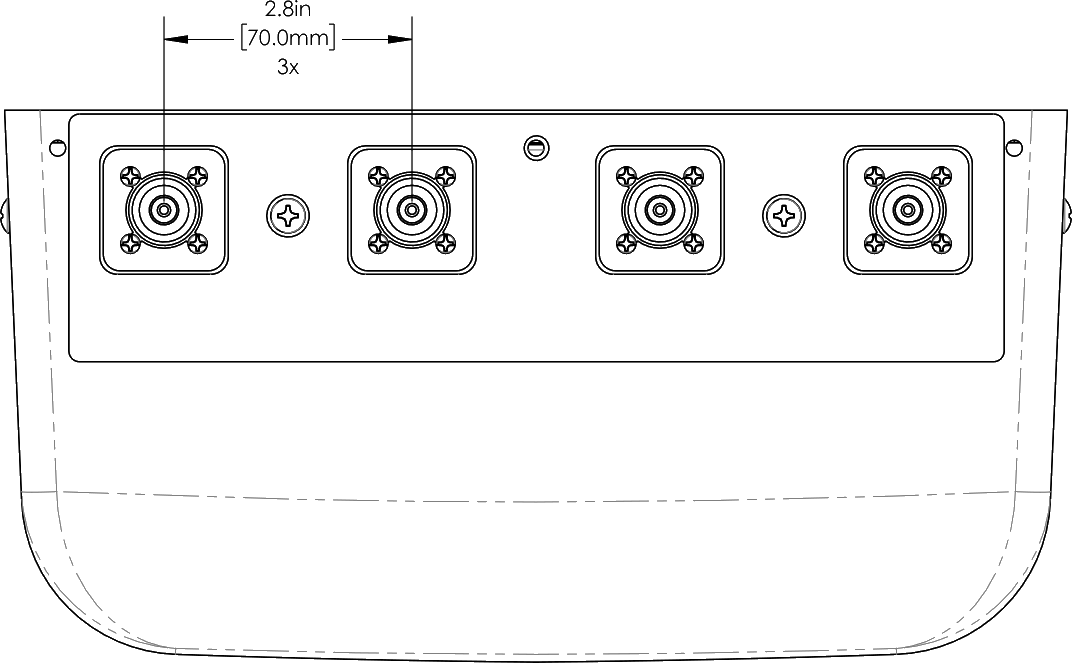
| Bottom View | ODA65F-KE1AA | ODA65F-KE1AB |
 |
 |
|
| Connector Spacing | ODA65F-KE1AA | ODA65F-KE1AB |
 |
 |
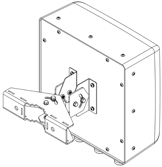
| Mounting Kit Views | |||
 |
 |
 |
|
| MBK-09 | MBK-08 | MBK-08 with optional MBC-07 |
| ODA65F-KE1AA-K | Antenna with 7-16 DIN connectors and MBK-09 non tilting wall mount |
| ODA65F-KE1AB-K | Antenna with 4.3-10 connectors and MBK-09 non tilting wall mount |
| ODA65F-KE1AA-K1 | Antenna with 7-16 DIN connectors and MBK-08 wall mount (adjustable tilt in both directions up to 45°) |
| ODA65F-KE1AB-K1 | Antenna with 4.3-10 connectors and MBK-08 wall mount (adjustable tilt in both directions up to 45°) |
| ODA65F-KE1AA-K2 | Antenna with 7-16 DIN connectors with MBK-08 and MBC-07 for pole mount (adjustable tilt in both directions up to 45°) |
| ODA65F-KE1AB-K2 | Antenna with 4.3-10 connectors with MBK-08 and MBC-07 for pole mount (adjustable tilt in both directions up to 45°) |
| MBK-09 | Fixed wall mount kit |
| MBK-08 | Adjustable wall mount kit |
| MBC-07 | Pole mount clamp for use with MBK-08 |
 | FREQUENCY BAND | |
 | 698-798 MHz |
 | 698-896 MHz |
 | 698-960 MHz |
 | 790-960 MHz |
 | 824-896 MHz |
 | 1695-1880 MHz |
 | 1695-2180 MHz |
 | 1695-2360 MHz |
 | 1695-2690 MHz |
 | 1850-1995 MHz |
 | 2300-2400 MHz |
 | 2300-2690 MHz |
 | 2496-2690 MHz |
 | 3300-3800 MHz |
 | 5150-5925 MHz |
 | NUMBER OF SECTORS | |
 | HEIGHT | |
 | HORIZONTAL BEAMWIDTH | |
 | NUMBER OF PORTS | |
 | LOW BAND PORTS | |
 | HIGH BAND PORTS | |
 |
|||